

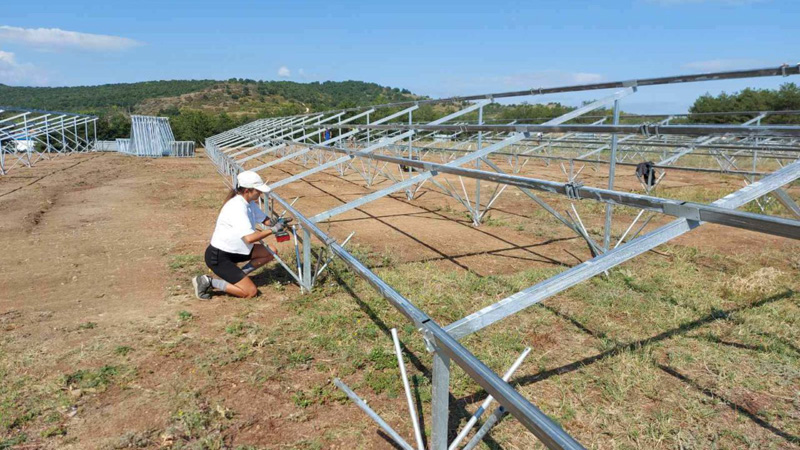
In areas prone to high winds—such as coastal regions, open Gobi deserts, and wind-prone sections of plains—wind loads are often the primary cause of failure in photovoltaic mounting structures. Many projects simply rely on wind speed as a reference, neglecting factors such as wind pressure, wind suction effects, and site exposure categories, which can easily lead to accidents such as modules being blown over, mounting structures deforming, and anchor bolts being pulled out. This article, in accordance with current Chinese codes and standards, clarifies the logic behind determining wind resistance ratings for photovoltaic mounting structures, as well as the core standards and key design considerations for practical implementation.
The core basis for wind-resistant design of photovoltaic mounting systems in China is the “Design Standard for Photovoltaic Power Stations” (GB 50797), the “Code for Loads on Building Structures” (GB 50009), and the “Technical Standard for the Application of Building-Integrated Photovoltaic Systems” (GB/T 51368). The design service life of mounting systems is set at 25 years, and wind loads are calculated based on the basic wind pressure corresponding to a 25-year return period, rather than instantaneous gusts—this is a key distinction from ordinary buildings. Wind exerts more than just forward thrust on PV arrays; the more dangerous force is the upward suction. The suction coefficient at the edges and corners of the array is significantly greater than in the central areas, and many wind-related failures begin with the failure of corner clamps or ground anchor bolts.
Wind resistance ratings cannot be directly equated to specific wind force levels. In engineering practice, the basic wind pressure w0 (kN/m²) is used as the design input, and the final standard wind load value is calculated by superimposing the height coefficient, gust coefficient, and shape coefficient. For typical inland projects, wind pressure is generally taken as 0.35–0.55 kN/m²; in coastal areas, regions prone to typhoons, and open, windy desert areas, it is generally ≥0.75 kN/m², and in areas subject to severe typhoons, it can reach 1.0 kN/m² or higher. At the same wind speed, wind pressure at unobstructed coastal sites, high elevations, and on rooftops will be significantly higher than in densely built-up urban areas. These must be classified according to site exposure categories and calculated separately; wind pressure parameters from neighboring cities cannot be directly applied.
When selecting and designing support structures for high-wind areas, emphasis must be placed on three key aspects: resistance to uplift, resistance to lateral displacement, and joint stiffness. For fixed supports, prioritize the use of thickened zinc-aluminum-magnesium profiles; increase the density of diagonal braces and add transverse tie rods; and reinforce corner joints with additional clamps and bolts. For foundations, prioritize the use of screw piles and cast-in-place piles, and minimize the use of counterweight foundations, as counterweight systems are highly susceptible to being lifted out of the ground as a whole under strong winds. Tracking brackets have a larger wind-facing surface area, resulting in more pronounced wind-induced vibration effects. In areas with high wind pressure, wind tunnel testing should be conducted when necessary to verify the wind vibration coefficient. At the same time, corrosion protection measures must be upgraded accordingly; since strong coastal winds are accompanied by salt spray, hot-dip galvanizing alone is unlikely to meet long-term service requirements.
Many projects fall into a common pitfall: proceeding directly with construction based solely on a generic load diagram. The code clearly stipulates that for projects with wind pressures exceeding 0.75 kN/m², distributed rooftop installations, complex topography, or tracking mount systems, standard design manuals cannot simply be applied. Instead, specialized structural calculation reports must be prepared to specify the stresses in structural members, the uplift resistance of anchor bolts, and displacement limits under various operating conditions. During the final inspection phase, calculation reports, material test reports, and bolt torque records must also be verified to ensure consistency between the design parameters and on-site installation.
FAQ
Q1:Is the wind resistance rating for photovoltaic mounting systems classified based on wind speed or wind pressure?
A:Engineering design uses basic wind pressure as the core indicator, while wind speed serves only as a reference for conversion. At the same wind speed, wind pressure can vary significantly between open coastal areas and sheltered urban areas; the code requires that the 25-year return period wind pressure for the project site be determined in accordance with GB50009, and that wind loads be calculated based on this value in combination with height and shape coefficient. It is not sufficient to rely solely on wind speed to determine whether the support structure is adequate.
Q2:In areas with strong winds, what are the wind-resistance advantages of fixed mounts compared to tracking mounts?
A:Fixed mounts have a fixed tilt angle and a stable wind-exposed area, resulting in reduced wind vibration effects and a controllable shape coefficient. Tracking mounts rotate with the sun, causing significant variations in wind suction and lateral thrust loads at different angles, which makes them more prone to vibration fatigue during gusts. For projects exposed to high wind pressures and frequent typhoons, fixed mounts are easier to verify, have lower reinforcement costs, and offer more controllable stability.
Q3:At what wind pressure level must photovoltaic mounting systems undergo wind tunnel testing?
A:For conventional fixed mounts, when wind pressure is ≤0.75 kN/m² and the site is simple and regular, the shape coefficient specified in the code may be used for calculations. However, when wind pressure is ≥1.0 kN/m², in coastal typhoon zones, for flexible mounts, long-span tracking mounts, or complex array configurations, it is recommended to conduct wind tunnel tests to refine the shape coefficient and wind vibration coefficient, thereby mitigating the risk of calculations based on code formulas resulting in an overly conservative design.
Add : 606, No. 12, Huasheng Road, Huli District, Xiamen,China
WhatsApp : +86153 9592 2968
Email : info@powerack.com



 English


